
1. Wprowadzenie
The Logicbus Z-SG is a versatile conditioner and isolator designed for strain gauge applications. It features a single input compatible with 4 or 6-wire load cells, providing analog voltage or current output, and supports Modbus RTU communication. This module is ideal for industrial measurement and control systems requiring precise signal conditioning.
Główne cechy obejmują:
- 1 input for 4 or 6-wire load cells with a configurable range of 1 to 64 mV/V.
- 1 analog output, configurable for current (0/4 to 20 mA) or voltage (0 to 5/10 Vdc).
- High 24-bit resolution for accurate measurements.
- Modbus RTU communication for integration into control systems (requires Z-PC-DINAL2-17.5).
- Flexible power supply options: 10 to 40 Vdc or 19 to 28 Vac.

Rysunek 1: Przód view of the Logicbus Z-SG Strain Gauge Input Module, showing terminal blocks and status indicators.
2. Konfiguracja i instalacja
Proper installation is crucial for the reliable operation of the Z-SG module. Ensure all connections are secure and follow local electrical codes.
2.1 Podłączenie zasilania
The Z-SG module accepts a wide range of power inputs. Connect the power supply to the designated terminals:
- Zasilanie DC: 10 do 40 V prądu stałego
- Zasilanie prądem zmiennym: 19 do 28 Vac
Upewnij się, że źródło zasilania spełnia określone wymagania dotyczące objętościtage and current requirements to prevent damage to the module.
2.2 Strain Gauge Input Wiring
Connect your 4-wire or 6-wire load cell to the strain gauge input terminals. Refer to the module's labeling for correct pin assignments for excitation, signal, and sense lines.

Rysunek 2: Szczyt view of the Z-SG module, illustrating the wiring terminals for power, strain gauge input, and communication.
2.3 Analog Output Wiring
Connect the analog output to your receiving device (e.g., PLC, data acquisition system). The output can be configured for either current or voltage:
- Prąd wyjściowy: 0/4 do 20 mA
- Tomtage Wyjście: 0 to 5 Vdc or 0 to 10 Vdc
2.4 Komunikacja Modbus RTU
For Modbus RTU communication, connect the module to a compatible RS-485 network. Note that a Z-PC-DINAL2-17.5 module may be required for proper integration. Refer to the Modbus communication protocol documentation for addressing and register details.
2.5 Konfiguracja
The input range (1 to 64 mV/V) and output type (current/voltage) are configurable via the RS-232 port using free software provided by the manufacturer. Connect the module to a computer via RS-232 and use the software to set the desired parameters for your application.
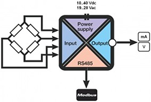
Rysunek 3: Functional block diagram illustrating the internal components and signal flow of the Z-SG module, including power supply, input, output, and Modbus communication.
3. Działanie
Once properly installed and configured, the Z-SG module will convert the strain gauge signal into the specified analog output or transmit data via Modbus RTU.
3.1 Konwersja sygnału
The module continuously monitors the strain gauge input and converts the mV/V signal into a proportional analog current or voltage output, as configured. This output can then be read by a control system to monitor load or force.
3.2 Komunikacja Modbus
For systems utilizing Modbus RTU, the module acts as a slave device, providing digital access to measured values and configuration parameters. Ensure your Modbus master device is correctly configured to communicate with the Z-SG module's address and baud rate.
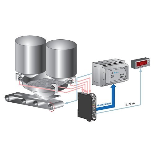
Rysunek 4: Example application diagram demonstrating the Z-SG module integrated into a weighing system, connecting load cells to a control unit via Modbus RTU and providing an analog output to a display.
4. Konserwacja
The Logicbus Z-SG module is designed for long-term, reliable operation with minimal maintenance. However, periodic checks can help ensure optimal performance.
- Kontrola wizualna: Okresowo należy sprawdzać moduł i jego połączenia pod kątem ewentualnych uszkodzeń fizycznych, luźnych przewodów lub korozji.
- Warunki środowiskowe: Aby zapobiec przedwczesnej awarii, należy upewnić się, że środowisko pracy mieści się w określonym zakresie temperatur i wilgotności.
- Czyszczenie: If necessary, gently clean the exterior of the module with a soft, dry cloth. Do not use harsh chemicals or abrasive materials.
- Rekalibracja: Depending on the application and required accuracy, periodic recalibration of the strain gauge system, including the Z-SG module, may be necessary. Refer to your system's calibration procedures.
5. Rozwiązywanie Problemów
If you encounter issues with your Z-SG module, consider the following troubleshooting steps:
- Brak zasilania: Sprawdź połączenia zasilania i upewnij się, że napięcie jest prawidłowe.tage is within the specified range (10-40 Vdc or 19-28 Vac). Verify that the power indicator LED on the module is illuminated.
- Nieprawidłowy wynik:
- Verify the strain gauge wiring for correct polarity and secure connections.
- Confirm the strain gauge is functioning correctly.
- Check the module's configuration via the RS-232 software to ensure the input range and output type are set correctly for your application.
- Ensure the receiving device (e.g., PLC) is correctly configured to read the analog output signal (current or voltagmi).
- Problemy z komunikacją Modbus:
- Verify RS-485 wiring, including termination resistors if necessary.
- Check the Modbus address and baud rate settings in both the Z-SG module (via configuration software) and the Modbus master device.
- Ensure the Z-PC-DINAL2-17.5 module, if used, is correctly installed and functioning.
- Observe the RX/TX indicator LEDs on the module for data transmission activity.
- Error Indicator (ERR LED): If the ERR LED is illuminated, consult the detailed product manual or contact technical support for specific error code interpretations.
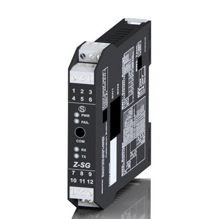
Rysunek 5: Strona view of the Z-SG module, highlighting the status LEDs (ERR, PWR, RX, TX, COM) which provide visual feedback on the module's operational status and communication activity.
6. Specyfikacje
| Funkcja | Wartość |
|---|---|
| Numer modelu | Z-SG |
| Typ wejścia | 1 input for 4 or 6-wire load cells |
| Zakres wejściowy | 1 ~ 64 mV/V (configurable) |
| Wyjście analogowe | Configurable: 0/4 ~ 20 mA or 0 ~ 5/10 Vdc |
| Rezolucja | 24-bit |
| Komunikacja | Modbus RTU (requires Z-PC-DINAL2-17.5 for full functionality) |
| Zasilacz | 10 ~ 40 Vdc or 19 ~ 28 Vac |
| Wymiary produktu | 6.89 x 3.94 x 4.41 cala |
| Waga | 4.94 uncji |
| Producent | Seneca (Brand: Logicbus) |
7. Gwarancja i wsparcie
For information regarding product warranty, technical support, or additional documentation, please contact Logicbus Inc. or visit their official webstrona.
Więcej informacji i danych kontaktowych znajdziesz na stronie Logicbus Store on Amazon.