1. Wprowadzenie
The MS8229 is an auto-ranging digital multimeter designed for professional and home use. It combines multiple measurement functions including AC/DC voltage and current, resistance, frequency, duty cycle, and capacitance. Additionally, it features built-in sensors for sound level, light (Lux), ambient temperature, and humidity, making it a versatile 5-in-1 testing instrument. Its large dual LCD display with backlight ensures clear readings in various conditions.

Rycina 1.1: Przód view of the MS8229 Digital Multimeter, showing the display, rotary switch, and input jacks.
2. Główne cechy
- Wyświetlacz: 4000 counts, large dual LCD with backlight.
- Zintegrowane czujniki: Built-in Sound Level Meter, Light Meter (Lux), Ambient Temperature, and Humidity Tester.
- Core Measurements: Testy AC/DC Voltage and Current, Resistance, Frequency, Duty Cycle, and Capacitance.
- Diode & Continuity: Diode Check and Continuity Test with audible buzzer (if resistance is less than 40 ohms).
- Pomiar temperatury: Type K thermocouple contact temperature measurement.
- Funkcje danych: Data Hold and Relative Measurement.
- Działanie: Auto Ranging / Selection.
- Wskaźnik zasilania: Wskaźnik niskiego poziomu naładowania baterii.
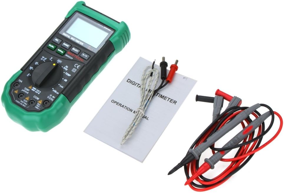
3. Zawartość opakowania
Po otwarciu opakowania prosimy sprawdzić, czy wszystkie wymienione poniżej elementy znajdują się w opakowaniu i są w dobrym stanie:
- 1 x MASTECH MS8229 Digital Multimeter
- 1 x Test Clip (Test Leads)
- 1 x Temperature Probe (Type K Thermocouple)
- 1 x Instrukcja w języku angielskim

Figure 3.1: The MS8229 Multimeter shown with its included test leads, temperature probe, and user manual.
4. Informacje dotyczące bezpieczeństwa
Aby zapewnić bezpieczną obsługę i serwis licznika, należy przestrzegać następujących środków ostrożności:
- Always ensure the meter is in the correct function and range for the measurement being taken.
- Nie stosować objętościtage or current that exceeds the maximum rated input for the selected range.
- Zachowaj ostrożność podczas pracy z objętościątagpowyżej 30 V AC RMS, 42 V szczytowo lub 60 V DC. Te wartościtagStwarzają ryzyko porażenia prądem.
- Przed zmianą funkcji lub zakresów należy odłączyć przewody pomiarowe od testowanego obwodu.
- Przed użyciem sprawdź przewody pomiarowe pod kątem uszkodzonej izolacji lub odsłoniętego metalu. W przypadku uszkodzenia wymień je.
- Nie należy używać miernika, jeśli wygląda na uszkodzony lub jeśli jego obudowa jest otwarta.
- Aby zapewnić dokładne odczyty, należy wymienić baterie, gdy tylko pojawi się wskaźnik niskiego poziomu naładowania.
- Adhere to all local and national safety codes.
5. Konfiguracja
5.1 Instalacja baterii
The MS8229 requires three (3) 1.5V AAA batteries (not included) for operation.
- Upewnij się, że miernik jest WYŁĄCZONY.
- Znajdź pokrywę komory baterii z tyłu miernika.
- Za pomocą śrubokręta poluzuj śrubę mocującą pokrywę baterii.
- Zdejmij pokrywę.
- Insert three AAA batteries, observing the correct polarity (+ and -) as indicated inside the compartment.
- Załóż pokrywę baterii i zabezpiecz ją śrubą.
Rysunek 5.1: View of the battery compartment, showing the slots for three AAA batteries and the fuse location.
5.2 Podłączanie przewodów pomiarowych
Prawidłowe podłączenie przewodów pomiarowych ma kluczowe znaczenie dla dokładności i bezpieczeństwa pomiarów.
- Dla większości tomówtage, resistance, frequency, capacitance, diode, and continuity measurements, insert the red test lead into the VΩ Hz gniazdo i czarny przewód pomiarowy do KOM podnośnik.
- For current measurements (mA/µA), insert the red test lead into the TEMP µA/mA gniazdo i czarny przewód pomiarowy do KOM podnośnik.
- For high current measurements (10A), insert the red test lead into the 10A gniazdo i czarny przewód pomiarowy do KOM podnośnik.
- For temperature measurements, connect the Type K thermocouple probe to the TEMP µA/mA I KOM gniazda, zwracając uwagę na biegunowość, jeśli ma to zastosowanie.

Figure 5.2: The MS8229 Multimeter with red and black test leads properly inserted into the input jacks.
6. Instrukcja obsługi
The MS8229 features a rotary switch for function selection and several buttons for additional features.

Figure 6.1: The MS8229 Multimeter display showing typical readings for humidity and temperature, along with a main measurement.
6.1 Rotary Switch Functions
Turn the rotary switch to select the desired measurement function:
- OFF: Turns the meter off.
- V~: AC Objętośćtagpomiar.
- V-: Objętość DCtagpomiar.
- Ω: Pomiar rezystancji.
- Dioda/Ciągłość: Diode test and Continuity test.
- Hz/Częstotliwość: Pomiar częstotliwości i współczynnika wypełnienia.
- TEMPERATURA: Temperature measurement using the Type K thermocouple.
- dB: Sound Level measurement.
- Lux / x10Lux: Light (Illumination) measurement.
- prawa strona: Relative Humidity measurement.
- Odp.: AC Current measurement (400µA to 10A).
- A-: DC Current measurement (400µA to 10A).
6.2 Funkcje przycisków
- HOLD/B.L: Press once to hold the current display reading. Press and hold to activate/deactivate the backlight.
- Hz/Częstotliwość: In Frequency/Duty Cycle mode, press to toggle between Hz and Duty Cycle display.
- REL: Aktywuje tryb pomiaru względnego, wyświetlając różnicę pomiędzy bieżącym odczytem a zapisaną wartością odniesienia.
- ZASIĘG: Manually selects the measurement range (overrides auto-ranging).
- WYBIERAĆ: Toggles between different functions within a single rotary switch position (e.g., AC/DC in voltage/current modes, Diode/Continuity).
- °C/°F: In Temperature mode, toggles between Celsius and Fahrenheit units.
6.3 Performing Measurements (Examplas)
6.3.1 Objętość DCtage Pomiar
- Ustaw przełącznik obrotowy w pozycji V-.
- Włóż czerwony przewód pomiarowy do VΩ Hz gniazdo i czarny przewód pomiarowy do KOM podnośnik.
- Podłącz przewody pomiarowe równolegle do napięcia stałegotagŹródło lub składnik podlegający pomiarowi.
- Przeczytaj tomtage wartość na wyświetlaczu.
6.3.2 Pomiar rezystancji
- Przed pomiarem rezystancji należy upewnić się, że obwód lub element jest odłączony od napięcia.
- Ustaw przełącznik obrotowy w pozycji Ω.
- Włóż czerwony przewód pomiarowy do VΩ Hz gniazdo i czarny przewód pomiarowy do KOM podnośnik.
- Connect the test leads across the component whose resistance is to be measured.
- Odczytaj wartość rezystancji z wyświetlacza.
6.3.3 Pomiar temperatury
- Ustaw przełącznik obrotowy w pozycji TEMP.
- Connect the Type K thermocouple probe to the TEMP µA/mA I KOM gniazda.
- Place the tip of the thermocouple probe on or near the object/area whose temperature is to be measured.
- Naciśnij ° C / ° F przycisk do przełączania pomiędzy stopniami Celsjusza i Fahrenheita.
- Odczytaj wartość temperatury na wyświetlaczu.
7. Konserwacja
7.1 Czyszczenie
Wyczyść obudowę za pomocą reklamyamp Ściereczką i łagodnym detergentem. Nie używaj środków ściernych ani rozpuszczalników. Utrzymuj zaciski wejściowe w czystości i bez zanieczyszczeń.
7.2 Wymiana baterii
When the low battery indicator appears on the display, replace the batteries as described in Section 5.1. Prompt battery replacement ensures continued accuracy and proper operation.
7.3 Wymiana bezpiecznika
The 10A input jack is protected by a resettable fuse. If the 10A current measurement function stops working, it indicates the fuse has tripped. Disconnect the meter from the circuit, turn it off, and wait a few moments for the fuse to reset. If the fuse continues to trip, check for short circuits or excessive current draw in your application.
7.4 Przechowywanie
If the meter is not to be used for an extended period, remove the batteries to prevent leakage and damage to the meter.
8. Rozwiązywanie Problemów
Jeżeli licznik nie działa prawidłowo, sprawdź następujące kwestie:
- Brak wyświetlacza lub wyświetlacz słabo widoczny: Sprawdź instalację baterii i w razie potrzeby wymień baterie.
- Nieprawidłowe odczyty: Ensure the correct function and range are selected. Verify test lead connections. Check for damaged test leads.
- „OL” lub wskaźnik przeciążenia: Zmierzona wartość przekracza wybrany zakres. Zmień zakres na wyższy lub upewnij się, że sygnał wejściowy mieści się w maksymalnych parametrach miernika.
- Pomiar prądu nie działa: Check if the 10A fuse has tripped (see Section 7.3). Ensure test leads are connected to the correct current input jacks.
- Continuity Buzzer Not Sounding: Ensure the resistance is below 40 ohms for the buzzer to activate.
Jeśli problemy będą się powtarzać, skontaktuj się z obsługą klienta.
9. Specyfikacje
| Typ pomiaru | Zakres / Wartość | Dokładność |
|---|---|---|
| Objętość DCtage (prąd stały) | 400m/4/40/400/1000V | 0.7% + 2 |
| AC Objętośćtage (ACV) | 400m/4/40/400V; 750V | 0.8%+3; 1%+3 |
| Prąd stały (DCA) | 400/4000µ/40m/400mA; 4/10A | 1.2%+3; 2.0%+10 |
| Prąd AC (ACA) | 400/4000µ/40m/400mA; 4/10A | 1.5%+5; 3.0%+10 |
| Opór | 400/4K/40K/400K/4MΩ; 40MΩ | 1.2%+5; 2%+5 |
| Pojemność | 40n/400n/4µ/40µ/100µF | 3.0% + 3 |
| Częstotliwość | 10/100/1K/10K/100KHz | 2.0% + 5 |
| Temperatura | -20 ~ 1000°C; 4 ~ 1832°F | 2.0% |
| Wilgotność względna (RH) | 20 do 95% | 5.0% |
| Światło (luks) | 4,000/40,000 Lux | 5.0% |
| Poziom dźwięku (dB) | 40 ~ 100dB | 3.5% |
| Test Diody | Tak | |
| Tester ciągłości | Buzzer if resistance < 40 ohms | |
| Cykl pracy | 0.1% - 99.9% | 3.0% |
| Zasilacz | 3 * 1.5V AAA batteries (not included) | |
| Wymiar | Wymiary (szer. x wys. x gł.) | |
| Waga produktu | 390g |
10. Gwarancja i wsparcie
This product is designed for reliability and performance. For any issues or inquiries not covered in this manual, please refer to your purchase documentation for warranty details or contact the retailer/manufacturer's customer support. Keep your purchase receipt as proof of purchase.