Wstęp
This manual provides detailed instructions for the installation, operation, and maintenance of the GIGABYTE GA-H110M-S2H GSM Micro ATX Motherboard. This motherboard supports LGA 1151 CPUs, DDR4 memory, and features SATA3 and USB 3.0/2.0 connectivity. Please read this manual thoroughly before proceeding with installation to ensure proper setup and functionality.
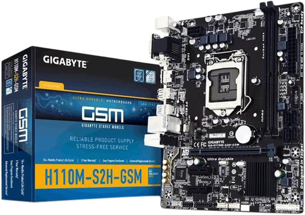
Figure 1: GIGABYTE GA-H110M-S2H GSM Motherboard and its retail packaging.
Konfiguracja i instalacja
Aby poprawnie zainstalować płytę główną i podzespoły, należy wykonać poniższe czynności.
1. Płyta główna ponadview

Rysunek 2: Widok z góry na dół view of the GIGABYTE GA-H110M-S2H GSM Motherboard, highlighting component placement.
2. Instalacja procesora (LGA 1151)
- Ostrożnie otwórz dźwignię mocującą gniazdo procesora.
- Align the CPU with the socket, ensuring the gold triangle on the CPU matches the indicator on the socket.
- Ostrożnie umieść procesor w gnieździe, nie używając siły.
- Zamknij dźwignię mocującą, aby zabezpieczyć procesor.
- Nałóż pastę termoprzewodzącą i zamontuj chłodnicę procesora zgodnie z instrukcją producenta.
3. Instalacja pamięci (RAM)
The motherboard features 2 DDR4 DIMM slots, supporting dual-channel, ECC, Non-ECC, unbuffered memory up to a maximum capacity of 32GB.
- Otwórz zaciski na obu końcach gniazda DIMM.
- Dopasuj moduł pamięci do gniazda, upewniając się, że wycięcie na module pokrywa się z wypustką w gnieździe.
- Naciśnij mocno oba końce modułu pamięci, aż klipsy zatrzasną się na swoim miejscu.
4. Montaż płyty głównej
- Zainstaluj osłonę I/O w obudowie komputera.
- Dopasuj płytę główną do wypustek w etui.
- Przymocuj płytę główną śrubami, upewniając się, że jest mocno osadzona.
5. Połączenia zasilania
- Podłącz 24-pinowe złącze zasilania ATX zasilacza do płyty głównej.
- Podłącz 8-pinowe (lub 4-pinowe) złącze zasilania ATX 12V do płyty głównej.
6. Storage Device Connections
The motherboard includes 4 SATA3 ports for connecting storage devices.
- Connect SATA data cables from your storage devices (HDDs, SSDs) to the SATA3 ports on the motherboard.
- Connect SATA power cables from your power supply to the storage devices.
7. Instalacja karty rozszerzeń
The motherboard provides 1 PCI-Express 3.0 x16 slot and 2 PCI-Express 2.0 x1 slots.
- Select an available PCI-Express slot.
- Remove the corresponding slot cover from your computer case.
- Insert the expansion card firmly into the slot until it is fully seated.
- Przymocuj kartę do obudowy za pomocą śrubki.
8. Panel przedni i złącza USB
- Connect the front panel headers (power switch, reset switch, HDD LED, power LED) to the corresponding pins on the motherboard. Refer to the motherboard diagram for pin assignments.
- Connect front panel USB 2.0/1.1 and USB 3.0/2.0 headers to the motherboard.
- Note: There is only one case fan connection on the motherboard. Additional fans may require a fan controller or molex connection to the PSU.
9. Połączenia tylnego panelu I/O

Figure 3: Rear I/O panel of the GIGABYTE GA-H110M-S2H GSM Motherboard, showing various ports.
Podłącz urządzenia peryferyjne do odpowiednich portów na tylnym panelu I/O:
- Porty PS/2: For PS/2 keyboard and mouse.
- Port VGA: For analog display connection.
- Port DVI-D: For digital display connection.
- Port HDMI: For high-definition audio/video output.
- Porty USB 3.0/2.0: For high-speed USB devices (2 rear ports).
- Porty USB 2.0/1.1: For standard USB devices (4 rear ports).
- Port LAN RJ45: Do podłączenia kabla sieciowego.
- Audio I/O Jacks: Do głośników, słuchawek i mikrofonów.
Instrukcja obsługi
1. Początkowy rozruch i dostęp do BIOS-u
- After completing all hardware connections, connect the power cord and turn on your system.
- During the boot process, press the Usuwać Naciskaj klawisz wielokrotnie, aby wejść do narzędzia konfiguracji BIOS-u.
- The GIGABYTE BIOS offers various options for system configuration. Navigate using the keyboard arrow keys and Wchodzić klawisz.
2. Instalacja systemu operacyjnego
Once in the BIOS, configure the boot order to prioritize your operating system installation media (USB drive or optical drive). Save changes and exit BIOS to begin the OS installation process.
3. Instalacja sterownika
After installing the operating system, install the necessary drivers from the GIGABYTE support website or the included driver CD (if applicable). Essential drivers include chipset, graphics (if using integrated), audio, and LAN drivers for optimal performance.
Konserwacja
Regularna konserwacja pomaga zapewnić długowieczność i stabilną pracę płyty głównej.
- Usuwanie kurzu: Okresowo czyść płytę główną i podzespoły sprężonym powietrzem z kurzu. Przed czyszczeniem upewnij się, że system jest wyłączony i odłączony od zasilania.
- Aktualizacje BIOS-u: Sprawdź GIGABYTE webOdwiedź witrynę, aby uzyskać najnowsze aktualizacje BIOS-u. Aktualizuj BIOS tylko w razie potrzeby i postępuj zgodnie z instrukcjami, aby uniknąć niestabilności systemu.
- Sprawdzanie komponentów: Sprawdź, czy wszystkie kable są solidnie podłączone i czy żaden element nie jest luźny.
Rozwiązywanie problemów
Jeśli napotkasz problemy, rozważ poniższe kroki rozwiązywania problemów:
- Brak wyświetlacza: Verify that the monitor is connected correctly to the appropriate video output (VGA, DVI-D, or HDMI) and that the monitor is powered on. Check if the CPU and RAM are properly seated.
- System się nie uruchamia: Ensure all power connectors (24-pin ATX, 8-pin/4-pin ATX 12V) are securely attached. Check RAM modules and CPU installation. Try booting with minimal components (CPU, one RAM stick, GPU if no integrated graphics).
- Problemy z urządzeniami peryferyjnymi: If USB devices or other peripherals are not working, ensure they are connected to the correct ports and that their drivers are installed.
- Niestabilność systemu: This can be caused by incompatible RAM, overheating, or outdated drivers. Check component temperatures and ensure all drivers are up to date.
- Resetowanie BIOS-u: If system settings prevent booting, clear the CMOS by removing the motherboard battery for a few minutes or using the CLR_CMOS jumper (refer to the motherboard diagram for location).
For further assistance, refer to the GIGABYTE official support webstrona.
Specyfikacje
Below are the technical specifications for the GIGABYTE GA-H110M-S2H GSM Motherboard:
| Funkcja | Specyfikacja |
|---|---|
| Gniazdo procesora | LGA 1151 |
| Zestaw układów scalonych | Intel H110 Express |
| Pamięć | 2 x DDR4 DIMM slots, Dual Channel, Max 32GB, DDR4-2133 MHz |
| Gniazda rozszerzeń | 1 x PCI-Express 3.0 x16, 2 x PCI-Express 2.0 x1 |
| Składowanie | 4 x SATA3 6Gb/s connectors |
| Porty USB | 4 x USB 3.0/2.0 (2 rear, 2 via header), 8 x USB 2.0/1.1 (4 rear, 4 via headers) |
| Wyjścia wideo | 1 x VGA, 1 x DVI-D, 1 x HDMI |
| Sieć lokalna | Gigabitowy Ethernet (GbE) |
| Audio | Dźwięk wysokiej rozdzielczości |
| Współczynnik kształtu | Mikro ATX |
| Wymiary | 23 x 12 x 11 cala (wymiary produktu) |
| Waga | 1.45 funta |
Gwarancja i wsparcie
Aby uzyskać informacje dotyczące gwarancji i pomocy technicznej, odwiedź oficjalną stronę internetową GIGABYTE website. Warranty terms and conditions may vary by region and retailer. It is recommended to register your product and retain your proof of purchase.
Wsparcie GIGABYTE: https://www.gigabyte.com/support