
1. Wprowadzenie
This manual provides essential information for the safe and effective installation, operation, and maintenance of your Intertherm OEM Upgraded Replacement Furnace Control Circuit Board, model 624564-0. This control board serves as the central processing unit for your furnace, managing various functions to ensure proper heating operation. Please read this manual thoroughly before attempting any installation or service.
2. Informacje dotyczące bezpieczeństwa
WARNING: Improper installation, adjustment, alteration, service, or maintenance can cause property damage, personal injury, or loss of life. Consult a qualified installer, service agency, or the gas supplier for information or assistance.
- Always disconnect electrical power to the furnace before installing or servicing the control board. Failure to do so can result in electrical shock or death.
- Upewnij się, że wszystkie połączenia przewodów są solidne i zgodne z lokalnymi i krajowymi przepisami elektrycznymi.
- This control board should only be installed by a qualified HVAC technician.
- Wear appropriate personal protective equipment (PPE), such as gloves and safety glasses, during installation and service.
- Do not operate the furnace with damaged components. Replace any faulty parts immediately.
3. Konfiguracja i instalacja
3.1. Zanim zaczniesz
- Verify that the replacement control board (model 624564-0) is compatible with your specific Intertherm furnace model.
- Gather necessary tools: screwdriver set, wire strippers, multimeter, and safety glasses.
- Take clear photographs of the existing wiring connections on the old control board for reference.
- Disconnect all electrical power to the furnace at the main breaker.
3.2. Kroki instalacji
- Odłączenie zasilania: Ensure the furnace's power supply is completely off. Confirm with a multimeter.
- Dostęp do starej tablicy: Otwórz panel dostępu do pieca, aby zlokalizować istniejącą płytę sterowniczą.
- Odłącz okablowanie: Carefully disconnect all wires from the old control board, labeling them if necessary to match your reference photos.
- Usuń starą tablicę: Odkręć lub wyjmij starą płytę sterowniczą z mocowania.
- Zainstaluj nową płytę: Mount the new Intertherm 624564-0 control board in the same location. Ensure it is securely fastened.
- Podłącz okablowanie: Reconnect all wires to the new control board according to your labels and reference photos. Double-check each connection for tightness and correct placement.
- Zamknij panel: Zamknij szczelnie panel dostępu do pieca.
- Przywróć zasilanie: Restore electrical power to the furnace at the main breaker.
- Operacja testowa: Rozpocznij cykl grzania, aby sprawdzić poprawność działania pieca. Obserwuj, czy nie pojawiają się kody błędów lub nie występuje nietypowe zachowanie.
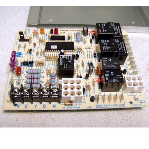
Figure 1: The Intertherm Furnace Control Circuit Board 624564-0. This image shows the front view of the circuit board with various terminals and components visible, illustrating its compact design and typical layout for furnace control.
4. Działanie
Once installed, the Intertherm 624564-0 control board operates automatically to manage the furnace's heating cycles. It receives signals from the thermostat, controls the igniter, gas valve, and blower motor, and monitors safety limits. The board typically features diagnostic LED lights that provide status indications and error codes to assist in troubleshooting.
4.1. Normal Operation Indicators
- Stała zielona dioda LED: Indicates normal operation and standby mode.
- Migająca zielona dioda LED: May indicate a call for heat or a specific operational stage (refer to furnace-specific documentation for exact flash codes).
- Stała czerwona dioda LED: Typically indicates a lockout condition or a fault.
- Migająca czerwona dioda LED: Indicates a specific error code. Count the flashes and refer to the troubleshooting section or your furnace manual.
5. Konserwacja
The Intertherm 624564-0 control board is designed for reliable, long-term operation with minimal maintenance. However, periodic inspection of the furnace system, including the control board, is recommended.
- Roczna inspekcja: Have a qualified technician inspect the furnace annually. This includes checking electrical connections, cleaning dust from components, and verifying proper operation of the control board.
- Zachowaj czystosc: Ensure the area around the control board is free from dust and debris, which can impede airflow and lead to overheating of components.
- Sprawdź okablowanie: Periodically check for any loose or corroded wiring connections to the control board.
6. Rozwiązywanie Problemów
This section provides guidance for common issues. For complex problems, always consult a qualified HVAC technician.
| Problem | Możliwa przyczyna | Rozwiązanie |
|---|---|---|
| Furnace not starting | No power to furnace; thermostat issue; safety limit tripped; faulty igniter. | Check circuit breaker; verify thermostat settings; reset furnace power; inspect igniter. |
| Silnik dmuchawy nie działa | Faulty blower motor; capacitor issue; control board fault; thermostat wiring. | Check blower motor connections; test capacitor; consult technician for board diagnosis. |
| Furnace cycles on and off rapidly (short cycling) | Dirty air filter; restricted airflow; oversized furnace; faulty thermostat. | Replace air filter; check ducts for obstructions; consult technician. |
| Diagnostic LED flashing red | Specific fault code (e.g., pressure switch, flame sensor, limit switch). | Count flashes and refer to your furnace's specific diagnostic chart for the corresponding error. Address the indicated component. |
7. Specyfikacje
- Numer modelu: 624564-0 (OEM Upgraded Replacement)
- Marka: Interterm
- Producent: Nordyna
- Waga przedmiotu: 20 uncji
- Numer części: OEM Upgraded Repl for 624564-0
- Funkcjonować: Tablica sterownicza pieca
8. Gwarancja i wsparcie
This Intertherm OEM Upgraded Replacement Furnace Control Circuit Board 624564-0 is typically covered by a manufacturer's warranty against defects in materials and workmanship. Specific warranty terms and duration may vary. Please retain your proof of purchase for warranty claims.
For technical support, warranty inquiries, or service, please contact your authorized Intertherm dealer or a qualified HVAC professional. Always provide the model number (624564-0) and your purchase date when seeking assistance.