
1. Wprowadzenie
The Altronix PD4 is a power distribution module designed to efficiently manage power delivery. It converts a single AC or DC input into four (4) individually fuse-protected outputs. This module is suitable for various low-voltage applications requiring reliable power distribution and circuit protection.
2. Informacje dotyczące bezpieczeństwa
Please read and understand all instructions before installing or operating the Altronix PD4. Failure to follow these instructions may result in injury or damage to the device.
- Zagrożenie elektryczne: Disconnect all power sources before installation or servicing.
- Prawidłowe łączenie: Always use fuses of the specified type and rating. Never bypass a fuse.
- Wentylacja: Aby zapobiec przegrzaniu, należy zapewnić odpowiednią wentylację wokół modułu.
- Wykwalifikowany personel: Instalację i serwisowanie powinien wykonywać wyłącznie wykwalifikowany personel.
- Zastosowanie wewnątrz: This device is intended for indoor use in a controlled environment.
3. Funkcje
- Four (4) individually fuse-protected outputs.
- Supports 12-24VDC input voltage.
- Total current output up to 10A.
- LED indicators for power status.
- Kompaktowa konstrukcja ułatwiająca integrację.
4. Specyfikacje
| Specyfikacja | Wartość |
|---|---|
| Wejście Voltage | 12-24 V prądu stałego |
| Całkowity prąd wyjściowy | 10A (maksymalnie) |
| Liczba wyjść | 4 (individually fused) |
| Wymiary produktu | 3.4 x 1.75 x 5.9 cala |
| Waga przedmiotu | 1 funt |
| Numer modelu | PD4 |
| Producent | Korporacja Altronix |
5. Konfiguracja i instalacja
Before proceeding, ensure all power is disconnected from the input source.
5.1. Montaż
The PD4 module can be mounted using screws through the designated mounting holes on the board. Choose a secure, dry location with adequate ventilation.
5.2. Połączenia okablowania
- Moc wejściowa: Connect the 12-24VDC power source to the input terminals labeled 'MAIN FUSE' or similar input terminals. Observe correct polarity (positive to positive, negative to negative).
- Urządzenia zewnętrzne: Connect your devices requiring power to the four (4) output terminal pairs (1P/1N, 2P/2N, 3P/3N, 4P/4N). Each output is individually protected by a fuse. Ensure the total current draw for all connected devices does not exceed 10A.
- Instalacja bezpiecznika: Insert the appropriate fuses into the designated fuse holders for each output. Refer to the markings on the board for recommended fuse ratings.
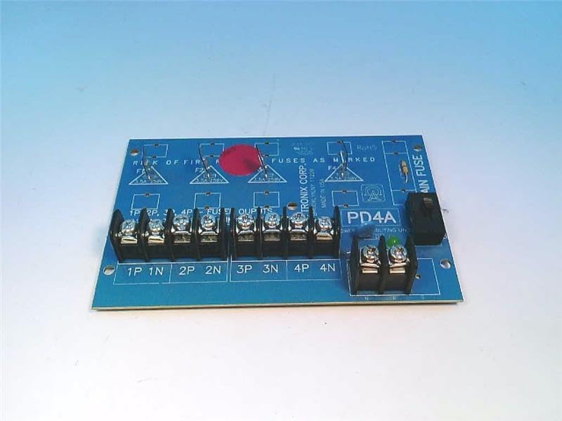
Figure 1: Altronix PD4 Power Distribution Module board, top view. Shows the main fuse holder, four sets of output terminals, and fuse locations for each output.

Figure 2: Altronix PD4 Power Distribution Module board, angled view. Highlights the terminal blocks for input and output connections, along with the fuse holders.
5.3. Włącz zasilanie
Once all connections are secure and fuses are in place, apply power to the input terminals. The power indicator LED (if present) on the board should illuminate, indicating proper power input.
6. Instrukcja obsługi
The Altronix PD4 operates automatically once power is supplied. It distributes the input power to the four connected output devices, with each output protected by its respective fuse. There are no user-adjustable settings or controls on the module itself beyond the initial wiring and fuse selection.
- Upewnij się, że głośność wejściowatage is within the specified 12-24VDC range.
- Monitor the power indicator LED to confirm the module is receiving power.
- If an output device is not receiving power, check its corresponding fuse.
7. Konserwacja
The Altronix PD4 requires minimal maintenance. Regular checks can help ensure continued reliable operation.
- Kontrola bezpiecznika: Periodically inspect fuses for any signs of damage or blowing. Replace blown fuses with the correct type and rating.
- Połączenia terminalowe: Ensure all terminal connections remain tight and secure. Loose connections can lead to intermittent power or overheating.
- Czyszczenie: Keep the module free from dust and debris. Use a soft, dry cloth for cleaning. Do not use liquid cleaners.
- Kontrola środowiskowa: Sprawdź, czy środowisko pracy mieści się w określonym zakresie temperatury i wilgotności.
8. Rozwiązywanie Problemów
| Problem | Możliwa przyczyna | Rozwiązanie |
|---|---|---|
| No power to any output, power LED off. | No input power, incorrect input voltage, main fuse blown. | Check input power source. Verify input voltage. Replace main fuse if blown (ensure correct rating). |
| No power to a specific output, other outputs working. | Blown fuse for that specific output, faulty wiring to the device. | Identify and replace the blown output fuse. Check wiring to the affected device. |
| Fuses blow frequently. | Overcurrent draw from connected device, short circuit in wiring or device. | Reduce load on the output. Inspect wiring and connected device for short circuits. Ensure correct fuse rating. |
| Module feels excessively hot. | Overload, insufficient ventilation, loose connections. | Reduce total load. Ensure adequate airflow. Tighten all terminal connections. |
9. Gwarancja i wsparcie
For warranty information and technical support, please refer to the official Altronix website or contact Altronix customer service directly. Keep your purchase receipt for warranty claims.
Korporacja Altronix
Webstrona: www.altronix.pl
Contact information can typically be found on their webstrona.