VOLTCRAFT GOS-632 FG
VOLTCRAFT GOS-632 FG Oscilloscope with Frequency Generator User Manual
1. Wprowadzenie
This manual provides essential information for the safe and efficient operation of your VOLTCRAFT GOS-632 FG Oscilloscope with Frequency Generator. Please read this manual thoroughly before using the device and keep it for future reference. The GOS-632 FG is a 30 MHz dual-channel analog oscilloscope integrated with a frequency generator, designed for various electronic measurement and testing applications.
2. Instrukcje bezpieczeństwa
Always observe the following safety precautions to prevent electric shock, injury, or damage to the instrument:
- Źródło zasilania: Podłączaj urządzenie wyłącznie do źródła zasilania o określonej mocy.tage i częstotliwość.
- Grunt: Aby zapobiec porażeniu prądem elektrycznym, należy upewnić się, że urządzenie jest prawidłowo uziemione.
- Wentylacja: Do not block ventilation openings. Ensure adequate airflow to prevent overheating.
- Środowisko: Operate the oscilloscope in a dry, clean environment, away from direct sunlight, high temperatures, and excessive dust or humidity.
- Sondy: Używaj wyłącznie sond przeznaczonych do pomiaru objętościtage and frequency being measured. Ensure probes are in good condition.
- Serwisowanie: Wszelkie prace serwisowe należy zlecać wykwalifikowanemu personelowi. Nie należy podejmować prób samodzielnego otwierania ani naprawy urządzenia.
- Kontakt z cieczą: Avoid contact with liquids. If liquid enters the device, disconnect power immediately and have it inspected by a qualified technician.
3. Zawartość opakowania
Please check the package contents upon receipt. If any items are missing or damaged, contact your dealer immediately.
- VOLTCRAFT GOS-632 FG Oscilloscope with Frequency Generator
- Przewód zasilający
- Two (2) Oscilloscope Probes (1x/10x switchable)
- Instrukcja obsługi (ten dokument)
4. Koniec produktuview
The VOLTCRAFT GOS-632 FG is a robust analog oscilloscope designed for reliable waveform analysis. Below is a general view urządzenia.
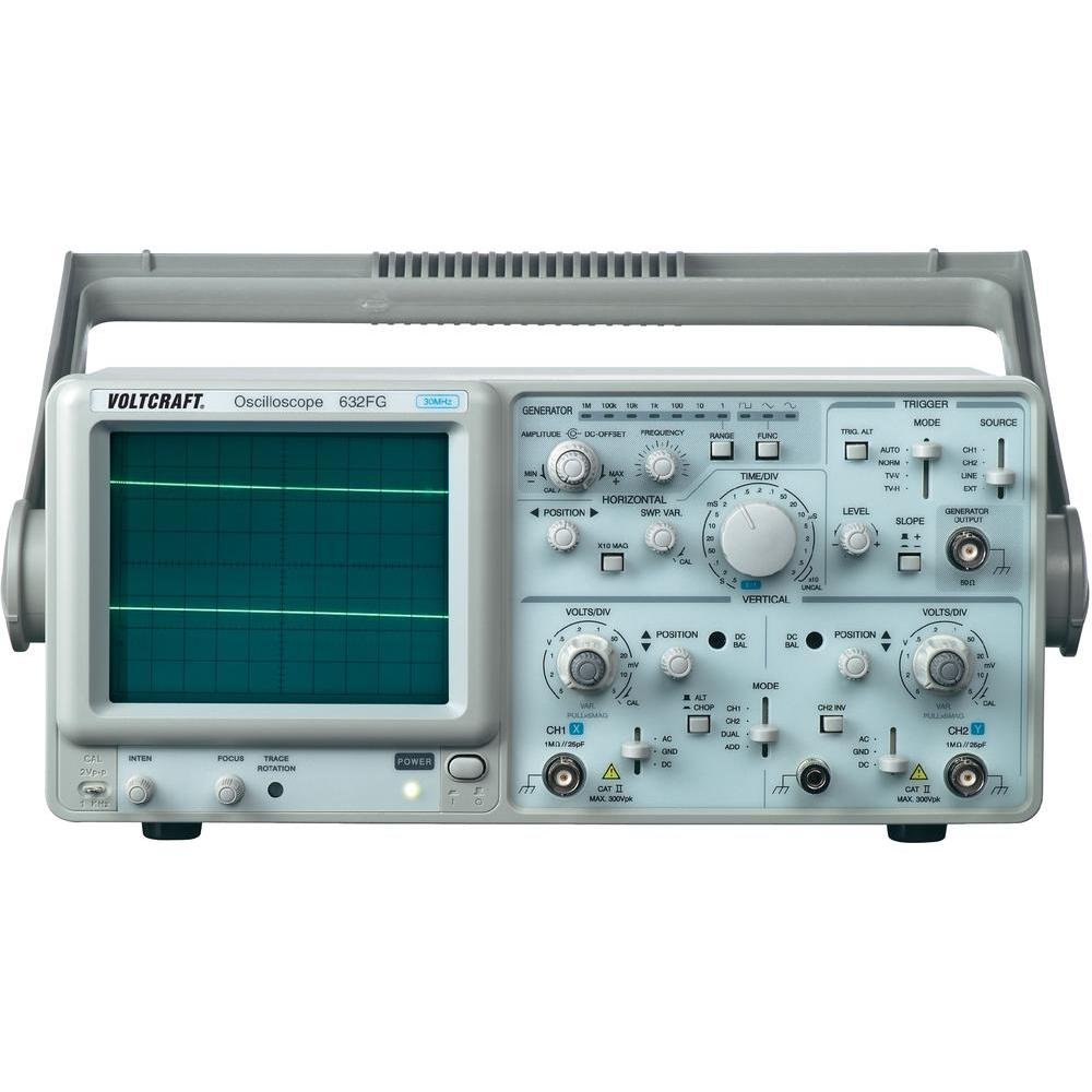
Rysunek 4.1: Przód view of the VOLTCRAFT GOS-632 FG Oscilloscope. This image shows the main display, control knobs, and input connectors for the two channels and the frequency generator output.
4.1. Elementy sterujące na panelu przednim
- CRT Display: Shows the waveform.
- CH1/CH2 Input: Złącza BNC do podłączania sond oscyloskopowych.
- VOLTS/DIV: Adjusts the vertical sensitivity for each channel.
- POZYCJA: Adjusts the vertical position of the waveform.
- TIME/DIV: Adjusts the horizontal sweep speed.
- TRIGGER LEVEL: Ustawia objętośćtage level at which the sweep starts.
- Sposób użycia: Selects trigger source (CH1, CH2, EXT, LINE).
- FREQUENCY GENERATOR OUTPUT: BNC connector for the integrated signal generator.
- FREQUENCY/AMPLITURDA: Controls for the frequency generator output.
- Przycisk zasilania: Włącza lub wyłącza urządzenie.
4.2. Złącza panelu tylnego
- Wejście zasilania prądem zmiennym: Złącze przewodu zasilającego.
- Terminal uziemiający: For additional grounding if required.
5. Konfiguracja
- Rozpakowywanie: Carefully remove the oscilloscope from its packaging. Retain the packaging for future transport.
- Umieszczenie: Place the oscilloscope on a stable, level surface with adequate ventilation around the unit.
- Podłączenie zasilania: Connect the supplied power cord to the AC power input on the rear panel and then to a grounded electrical outlet.
- Połączenie sondy: Connect the oscilloscope probes to the CH1 and/or CH2 BNC input connectors on the front panel. Ensure a secure connection.
- Kompensacja sondy: Before taking measurements, compensate your probes. Connect the probe tip to the probe compensation output (usually a square wave signal on the front panel) and adjust the probe's compensation trimmer until a flat-top square wave is displayed.
6. Obsługa oscyloskopu
6.1. Pomiar podstawowy
- Włączanie: Press the POWER switch to turn on the oscilloscope. Allow a few minutes for the display to stabilize.
- Sygnał wejściowy: Connect the probe to the circuit point you wish to measure.
- Vertical Adjustment (VOLTS/DIV & POSITION):
- Select the appropriate VOLTS/DIV setting to display the waveform within the screen.
- Use the POSITION knob to center the waveform vertically.
- Horizontal Adjustment (TIME/DIV & POSITION):
- Select the appropriate TIME/DIV setting to display several cycles of the waveform horizontally.
- Use the horizontal POSITION knob to move the waveform left or right.
- Trigger Setup:
- Set the TRIGGER MODE (e.g., AUTO, NORM).
- Adjust the TRIGGER LEVEL knob until a stable waveform is displayed.
- Select the TRIGGER SOURCE (e.g., CH1, CH2).
6.2. Using the Frequency Generator
- Podłącz wyjście: Connect a BNC cable from the FREQUENCY GENERATOR OUTPUT to the circuit or device under test.
- Ustaw częstotliwość: Use the FREQUENCY control to select the desired output frequency.
- Ustawić Ampliturgia: Użyj AMPLITUDE control to adjust the output signal strength.
- Wybór kształtu fali: If available, select the desired waveform type (e.g., sine, square, triangle).
7. Konserwacja
- Czyszczenie: Przed czyszczeniem odłącz przewód zasilający. Użyj miękkiej,amp cloth with a mild detergent to clean the exterior. Do not use abrasive cleaners or solvents.
- Składowanie: When not in use for extended periods, store the oscilloscope in a dry, dust-free environment.
- Kalibrowanie: For accurate measurements, periodic calibration by qualified personnel is recommended.
8. Rozwiązywanie Problemów
| Problem | Możliwa przyczyna | Rozwiązanie |
|---|---|---|
| Brak wyświetlania po włączeniu zasilania | No power, brightness/focus too low | Check power cord, outlet. Adjust INTENSITY and FOCUS knobs. |
| Niestabilna forma fali | Incorrect trigger settings, signal too noisy | Adjust TRIGGER LEVEL, TRIGGER MODE, and TRIGGER SOURCE. Check signal integrity. |
| Brak sygnału | Probe not connected, incorrect VOLTS/DIV, signal outside range | Ensure probe is connected and making contact. Adjust VOLTS/DIV and POSITION. Check probe compensation. |
| Frequency generator output not working | Output cable not connected, amplitude set to zero | Check output cable connection. Increase AMPŚWIATŁO. |
9. Specyfikacje
| Funkcja | Szczegół |
|---|---|
| Numer modelu | GOS-632 FG |
| Producent | VOLTCRAFT |
| Przepustowość łącza | 30 MHz (DC) |
| Kanały | 2 kanałów analogowych |
| Integrated Function | Generator częstotliwości |
| Waga produktu | 9.07 g (Note: This weight seems unusually low for an oscilloscope and might be a data entry error. Refer to product packaging for accurate weight.) |
| ASIN | B003IDBEYM |
| Pierwszy dostępny | 31 marca 2015 r. |
10. Gwarancja i wsparcie
VOLTCRAFT products are designed for quality and reliability. For information regarding warranty terms, technical support, or service, please refer to the warranty card included with your product or visit the official VOLTCRAFT webNie próbuj samodzielnie naprawiać urządzenia, ponieważ może to spowodować utratę gwarancji.
For further assistance, please contact your local VOLTCRAFT distributor or customer service center.