1. Wprowadzenie
This manual provides essential information for the safe and efficient installation, operation, and maintenance of your Hormann EL301 Disposable Light Barrier. Please read these instructions carefully before beginning installation or use. Keep this manual for future reference.
The Hormann EL301 is designed for use as an additional safety device in both indoor and outdoor environments. It helps detect obstructions in the path of automated systems, such as garage doors or gates, enhancing overall safety.
Informacje dotyczące bezpieczeństwa
- Upewnij się, że wszystkie połączenia elektryczne zostały wykonane przez wykwalifikowanego elektryka i są zgodne z lokalnymi przepisami.
- Przed przystąpieniem do prac instalacyjnych, konserwacyjnych lub naprawczych należy odłączyć zasilanie.
- Do not modify the device in any way. Unauthorized modifications can lead to malfunction and void the warranty.
- The device is rated IP65, providing protection against dust and low-pressure water jets. However, avoid submerging the unit.
- Regularly inspect the light barrier for any signs of damage or obstruction.
2. Zawarte komponenty
Sprawdź, czy w Twoim opakowaniu znajdują się wszystkie wymienione poniżej elementy:
- 2 x EL301 Photocell Units (Transmitter and Receiver)
- 2 x wsporniki montażowe
- 2 x 10m Connection Cables (2-wire round cable)
- Mounting Hardware (screws, anchors - typically included)
Rysunek 1: Koniecview of Hormann EL301 Light Barrier components.
3. Instalacja i konfiguracja
Follow these steps for proper installation of your EL301 light barrier:
- Wybierz miejsce montażu: Select a location where the transmitter and receiver units can be mounted directly opposite each other, ensuring an unobstructed line of sight. The height should be appropriate for detecting the intended objects (e.g., vehicle bumpers, people).
- Uchwyty montażowe: Securely attach the mounting brackets to a stable surface using the provided hardware. Ensure they are level and aligned.
- Install Photocell Units: Slide the EL301 photocell units onto the mounting brackets. The units should face each other.
- Okablowanie:
- Connect the 2-wire connection cables to the respective terminals on each photocell unit. Refer to your automated system's manual for specific wiring diagrams for the control unit.
- The EL301 units are typically connected to the safety input of a gate or garage door operator.
- Ensure proper polarity if specified by your control unit.
- Wyrównanie: Once powered, align the transmitter and receiver units. Most units have an indicator light that illuminates or changes color when proper alignment is achieved. Adjust the position of the units until the indicator shows a strong signal.
- Funkcjonalność testu: After alignment, test the light barrier by breaking the beam with an object. The automated system should react as expected (e.g., stop or reverse).

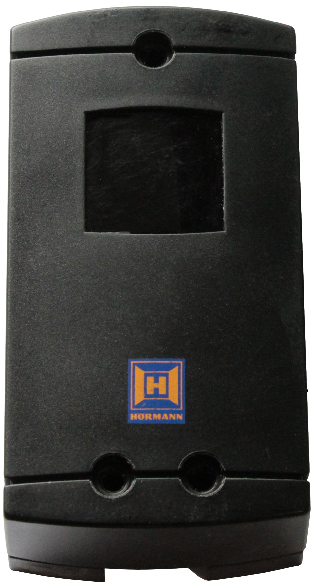
Figure 2: Hormann EL301 Photocell Units.
4. Działanie
The Hormann EL301 Light Barrier operates by emitting an infrared beam from the transmitter unit to the receiver unit. When this beam is interrupted by an object, the receiver signals the connected control unit (e.g., gate or garage door operator) to perform a predefined safety action, such as stopping or reversing movement.
The system is continuously active when the connected automated system is powered on. No user interaction is typically required for its operation once properly installed and aligned.
5. Konserwacja
Regular maintenance ensures the longevity and reliable operation of your light barrier:
- Czyszczenie: Okresowo czyść soczewki nadajnika i odbiornika miękką, miękką szmatką.amp szmatka. Kurz, brud, pająkwebs, or other debris can obstruct the beam and cause false triggers or malfunctions.
- Kontrola: Regularly check the mounting brackets and cables for any signs of damage, corrosion, or loose connections. Ensure the units remain securely mounted and properly aligned.
- Ochrona środowiska: While rated IP65, extreme weather conditions (heavy snow, ice, prolonged heavy rain) can temporarily affect performance. Ensure proper drainage around the units.
6. Rozwiązywanie Problemów
| Problem | Możliwa przyczyna | Rozwiązanie |
|---|---|---|
| Light barrier not functioning / System not responding. |
|
|
| False triggers / System stops without obstruction. |
|
|
7. Specyfikacje
| Model | EL301 |
| Numer części | 436233 |
| Marka | Hormanna |
| Klasa ochrony | IP65 (Pyłoszczelność i ochrona przed strumieniami wody o niskim ciśnieniu) |
| Aplikacja | Wewnątrz i na zewnątrz |
| Kabel połączeniowy | 2 x 10m round cable, 2 wires |
| Wymiary (dł. x szer. x wys.) | Wymiary 20 x 15 x 3.5 cm |
| Waga | 630 gramów |
| Tworzywo | Plastikowy |
| Kraj pochodzenia | Niemcy |
8. Gwarancja i wsparcie
For warranty information and technical support, please contact your authorized Hormann dealer or visit the official Hormann webZachowaj dowód zakupu na wypadek roszczeń gwarancyjnych.
Notatka: The manufacturer continually strives to improve its products. Therefore, the information in this manual may be subject to change without prior notice.